
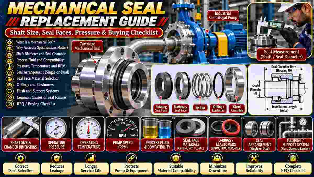
Are you replacing a leaking mechanical seal in a centrifugal pump, chemical processing system, or industrial fluid-handling application? Ordering the wrong seal can result in installation problems, recurring leakage, and premature equipment failure.
Mechanical seal replacement specifications should include shaft diameter, seal chamber dimensions, process fluid, operating pressure, temperature, rotational speed, seal arrangement, face materials, and secondary sealing components.
Asar Engineering Pvt. Ltd. offers mechanical seals for industrial rotating equipment.
A mechanical seal is a sealing assembly that controls fluid leakage where a rotating pump shaft passes through a stationary housing.
Typical components include:
Rotating seal face.
Stationary seal face.
Springs or bellows.
O-rings or gaskets.
Gland components.
Shaft sleeve, where applicable.
Explore Mechanical Seals for product information.
Accurate specifications help ensure the replacement fits the equipment and withstands its operating conditions.
Incorrect selection may lead to:
Fluid leakage.
Damaged sealing faces.
Chemical incompatibility.
Excessive heat.
Installation difficulties.
Unexpected downtime.
A replacement must be evaluated against the complete pump arrangement.
Measure the shaft or sleeve diameter at the actual seal mounting location using suitable measuring instruments.
Check:
Shaft diameter.
Sleeve diameter, if fitted.
Surface condition.
Shaft tolerances.
Wear or scoring.
Relevant shoulder dimensions.
Do not select a replacement seal using an approximate shaft measurement.
Seal chamber dimensions determine whether the replacement seal can be installed with adequate clearance and correct gland mounting.
Important dimensions include:
Seal chamber bore.
Available axial space.
Gland mounting dimensions.
Bolt positions.
Shaft-to-chamber clearance.
Required installation length.
Provide the pump manufacturer's seal chamber drawing whenever possible.
Process fluid determines important requirements for seal face materials, secondary seals, corrosion resistance, and flushing arrangements.
Specify:
Fluid name.
Chemical concentration.
Viscosity.
Abrasive particle content.
Corrosive characteristics.
Crystallization tendency.
Cleaning chemicals.
Chemical compatibility should be evaluated under actual operating conditions.
Seal chamber pressure and temperature influence the mechanical seal's material suitability, face loading, and operating limits.
Provide normal and maximum conditions, including startup and shutdown requirements where relevant.
The selected assembly must be rated for the actual service.
Avoid assuming that seals with similar dimensions have identical operating limits.
Pump speed influences seal face surface velocity, heat generation, and the suitability of the sealing arrangement.
Provide:
Normal operating RPM.
Maximum RPM.
Rotation direction.
Continuous or intermittent duty.
Starting frequency.
High-speed applications may require additional design considerations.
Seal face materials should be selected according to fluid chemistry, lubrication conditions, abrasiveness, temperature, and operating pressure.
Common materials include:
Carbon graphite.
Silicon carbide.
Tungsten carbide.
Other specialized materials.
Carbon-based and hard-face combinations are used in different applications.
The correct pairing should be confirmed with the seal supplier.
O-rings and other secondary seals help prevent leakage around the mechanical seal's non-face sealing interfaces.
Common material options include:
EPDM.
FKM.
NBR.
PTFE-based components.
No elastomer is suitable for every chemical or temperature.
Confirm compatibility with the process liquid and cleaning fluids.
A single mechanical seal uses one primary sealing interface, while a dual arrangement incorporates two sealing interfaces and may require a support-fluid system.
Dual arrangements may be considered for hazardous, poorly lubricating, or otherwise demanding fluids.
Selection depends on leakage requirements, pressure conditions, process risks, and the appropriate support system.
A dual seal is not automatically necessary for every pump.
A cartridge seal is supplied as a preassembled unit, while a component seal requires individual sealing elements to be installed and adjusted.
Cartridge seals can simplify installation in compatible equipment.
However, the correct shaft, chamber, gland, and setting dimensions remain essential.
Confirm the required configuration before ordering.
Flushing, cooling, and support-fluid arrangements help maintain suitable conditions around the seal faces.
Depending on the application, a system may require:
Process-fluid recirculation.
External flushing.
Cooling.
Buffer fluid.
Barrier fluid.
Monitoring instruments.
Applicable API 682 requirements should be specified for relevant process-pump applications.
Support arrangements must match the selected seal and pump design.
Common causes include dry running, excessive heat, abrasive contamination, incorrect installation, shaft problems, and unsuitable material selection.
Warning signs include:
Increased leakage.
Abnormal vibration.
Seal face damage.
Excessive temperature.
Damaged O-rings.
Repeated seal failures.
Investigate the pump and operating conditions before installing another replacement.
Inspect the original seal, pump shaft, seal chamber, and operating conditions before selecting the replacement.
Record the existing seal model, dimensions, face materials, and observed failure symptoms.
Also inspect the sleeve, bearings, shaft runout, and cooling or flushing system.
Replacement should follow approved isolation and installation procedures.
Prices depend on seal size, arrangement, materials, pressure rating, construction, customization, and inspection requirements.
Additional factors may include specialized elastomers, cartridge construction, and seal support components.
Compare quotations using equivalent technical specifications.
A complete quotation request should identify the pump, sealing arrangement, process conditions, materials, and replacement dimensions.
Provide:
Pump manufacturer and model.
Existing mechanical seal designation.
Shaft or sleeve diameter.
Seal chamber and gland dimensions.
Process fluid and concentration.
Normal and maximum pressure.
Operating temperature.
Rotational speed.
Single or dual seal requirement.
Seal face and elastomer specifications.
Flushing or support system details.
Drawings, quantity, and delivery location.
Include photographs or an existing seal sample when available.
Common questions concern dimensions, materials, seal types, and recurring leakage.
No. Seal chamber dimensions, fluid properties, operating conditions, and construction details must also match.
Yes. Silicon carbide is used in suitable seal face combinations, subject to application requirements.
They can simplify installation when properly matched to the equipment.
Possible causes include installation errors, unsuitable materials, shaft problems, inadequate lubrication, or incorrect operating conditions.
Custom configurations may be available based on approved specifications and supplier capabilities.
You can request a quotation by sharing your pump model, existing seal details, shaft dimensions, process conditions, materials, and quantity.
For replacement projects, include a technical drawing or sample whenever possible.
Explore Mechanical Seals or contact Asar Engineering to discuss your requirements.
Technical Note: Final seal selection and installation must follow approved pump specifications, manufacturer operating limits, chemical compatibility requirements, and applicable safety standards.